32+ The Most Complete Bjt Amplifier Circuit Diagram. Thats a simple audio amplifier transistor/bjt circuit. The circuit diagram for a bjt differential amplifier is shown below: In almost all books voltage.
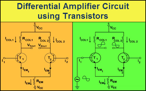
32+ The Most Complete Bjt Amplifier Circuit Diagram In this case, if the v1 at q1 is sinusoidal, then as v1 goes on increasing, the transistor starts to conduct and this results in a heavy collector current ic1 increasing the voltage drop across rc1, causing a decrease in vo1.
Explain why the ac voltage gain (av. Constant over the temperature ranges. An amplifier circuit is used to increase the strength of the signal. Amplifier circuits with bjt or mosfet.
How to obtain ac equivalent circuit? The rationale behind a complementary pair cascade the cascode circuit can be built using the same type transistors, or even mixed with one fet and one bjt. Explain the principle used in the measurement of output resistance of the. That's mean this circuit uses two ic's of every single channel in bridge mode.
Circuit diagram of common emitter bjt amplifier is given in fig.2. This is the circuit design of 21w class ab audio amplifier uses power transistors as the main part. Transistor audio amplifier circuit diagram. Amplifier power dissipation • static power dissipation in amplifiers is determined from their dc equivalent circuits.