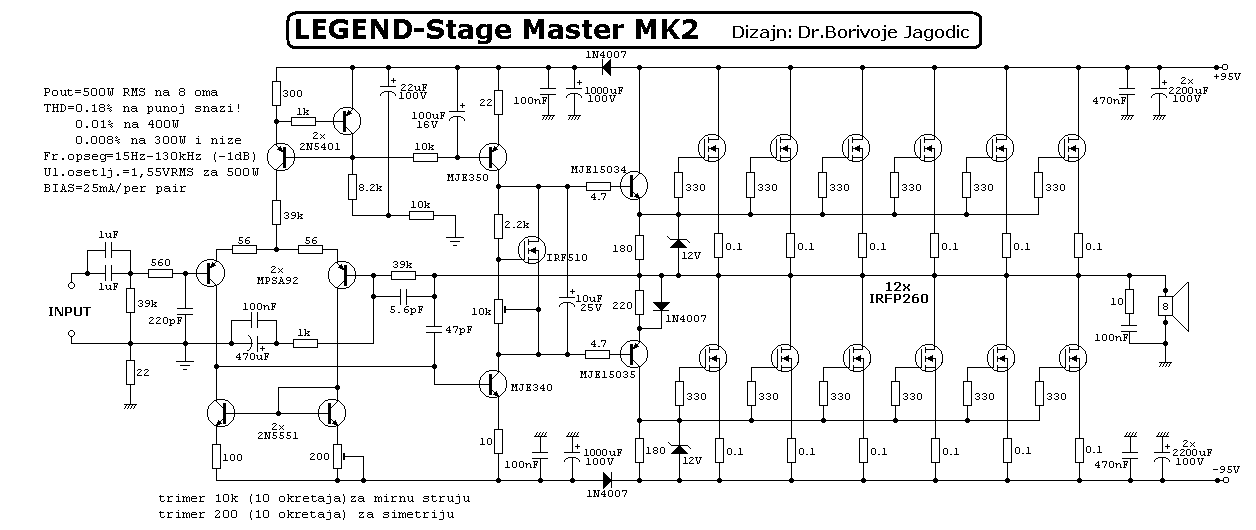
11+ Best 1000 Watt Amplifier Driver Board Circuit Diagram. The proposed topology has high efficiency (more than 90%) when operating at nominal power. Simple audio amplifier schematic diagram using transistor. The input mains 220v or 120v ac is half wave rectified by d1 at about 14.5v at vdd, the current sources gets switched off and forces the ic circuitry into an oscillatory mode or initiates pulsing of the ic.

11+ Best 1000 Watt Amplifier Driver Board Circuit Diagram I have made this circuit for more than 1000 times if you are in search of pcb of this circuit then inbox me.
Here is a schematic diagram of a diy headphone amp circuit which will increase or amplify the audio in your headphones. Super high power amplifier called yiroshi audio is most powerful it has output power about 1000w up to 3000w, you can see the circuit diagram, pcb layout amplifier, and see the video test yiroshi audio. This block diagram represents typical smps inner blocks. However since the idea presented here does not include a cd or a memory card driver circuit, the the circuit discussed here is intended specifically for car audio applications and provides a simple.
The power supply needed for this circuit should be 10a minimum single channel and 20a for stereo channel. I am not a hifi geek, i just wanted to build a simple stereo amplifier that could drive some although, i was looking for a way to turn this into a 5 watt mono amp on the datasheet. If you want another post then please visit our website. In the circuit with 100 watts, 1.
You will get the free circuit and pcb layout here. You can use this headphone. 150 watt amplifier circuit diagram. 1600 x 1099 jpeg 156kb.